The following is an example of how to setup and configure the HP Simware network simulator 7.1.50. We will setup a basic lab of 3 HP switches, 2 of which will be in an IRF stack, and the 3rd breaking out to a physical Cisco router, which will inject routes into the topology. Below details the topology that we will be creating, and the routing protocols to be configured.

Before installing the Simware application, it is a requirement to have Oracle Virtualbox version 4.2.18 or above installed. The installation of Virtualbox is a very simple process. Virtualbox can be downloaded free from http://www.virtualbox.org
For this guide Virtualbox 4.3.14 was installed, accepting all default options.
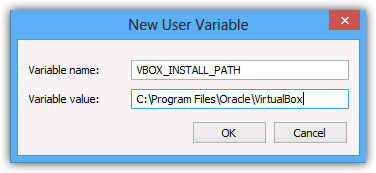
Before installing HNS, a new environment variable needs creating, as shown below, with the relevant install path for your installation of Virtualbox.
Download the Simware package from http://h17007.www1.hp.com/us/en/networking/products/simulator/#.U_21DEhM4lE once downloaded, extract the .rar file, which will contain the setup application, and various user guides.
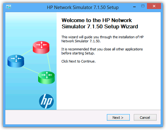
- Launch HNS_7.1.50-Setup.exe.
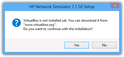
- With Virtualbox versions 4.2.24 and later, HNS will generate the error below, confirm that the environment variable as been added and click yes to continue with the installation.
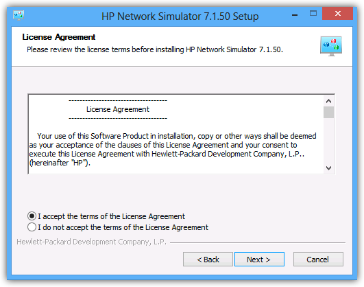
- The installation from here on, is straight forward accepting defaults.

- The installation is now complete.
- Launching HNS will open up the following window, this is where we will create the topology.
- Below is an extract from the Simware user guide showing a small selection of the available devices.
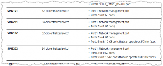
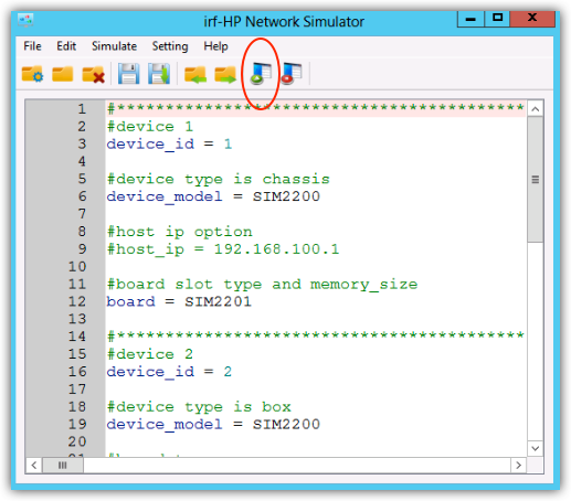
The first stage in building the configuration file is to define the devices, the various models available include box switches, routers, and chassis based switches and routers. The primary decision to select a particular model, will be based upon the ports required for the lab. The following shows the minimum configuration required for the switches that will be used within this lab. All 3 devices are box switches with 8x Gbe ports, with all the centralised and MPU devices, port 1 will always be assigned to the management port.
#device 1
device_id = 1
#device type is box
device_model = SIM2200
#board type
board = SIM2201
#*********************************************************************
#device 2
device_id = 2
#device type is box
device_model = SIM2200
#board type
board = SIM2201
#*********************************************************************
#device 3
device_id = 3
#device type is box
device_model = SIM2200
#board type
board = SIM2201
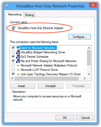
Once the devices are selected and defined, the next step is to define the connectivity for the devices. Prior to defining the management port, you should take note of the name of the virtual adapter as indicated below, that was installed as part of the Virtualbox install, this will allow telnet/ssh access to the device. The management ports of the device when configured later, should be on the same subnet as this virtual adapter.
The below configuration demonstrates the connectivity map that will be used for this lab, this will provide the connectivity as per the topology diagram. Within the configuration you can see that the management ports (port 1) of all devices are mapped to the host virtual adapter for telnet/ssh access later in the lab. Further to this the inter-switch links are defined, and finally device 3 is mapped to a spare physical NIC to allow break out and connection to a physical Cisco router. The same method should be used as above when noting the name of the NIC mapped to.
#connect host interface
device 1 : interface 1 host : “VirtualBox Host-Only Ethernet Adapter”
device 2 : interface 1 host : “VirtualBox Host-Only Ethernet Adapter”
device 3 : interface 1 host : “VirtualBox Host-Only Ethernet Adapter”
#connect switch interfaces
device 1 : interface 2 device 2 : interface 2
device 1 : interface 3 device 2 : interface 3
device 1 : interface 4 device 3 : interface 4
device 2 : interface 5 device 3 : interface 5
#connect to physical router
device 3 : interface 2 host : “Broadcom BCM5716C NetXtreme II GigE (NDIS VBD Client) #32″
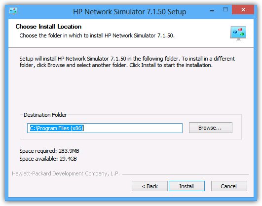
Once the configuration file is complete, save it as a new project, NHS will not allow you to run the project until you have saved it. If you have made errors in the config, these will be hi-lighted with a reason. Below displays the completed project file, with the run button hi-lighted.
Once you click run, NHS should then automatically run Virtualbox, with the defined devices, as shown below.
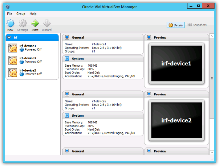
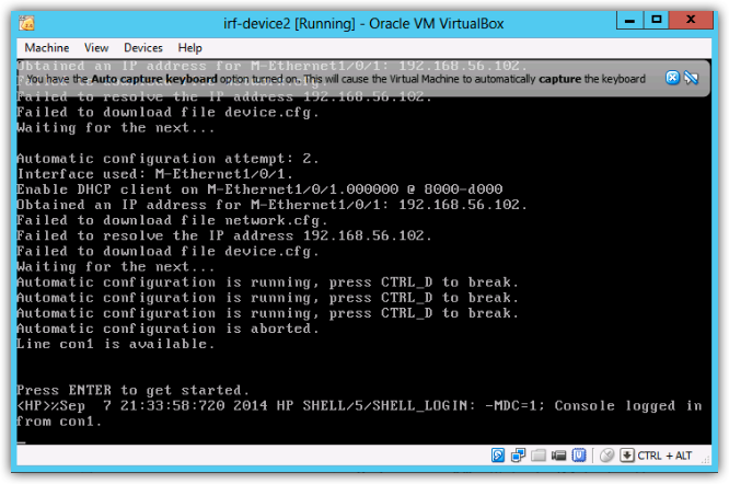
You can see in this example that the project was saved as ‘irf’ , the virtual devices are then automatically named this with the device number appended. You can now select the virtual machines and start each one in turn, once a machine begins booting a Virtualbox console screen will appear as below, at this point all configuration must be done through this console session, unfortunately the console screen does not support copy/paste or scroll-back, so you will want to configure management access before doing much configuration work. When the device first boots, it is attempting to auto-configure looking for config files, you should break out of this with CRTL-D.
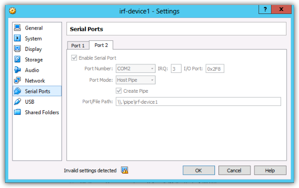
All 3 devices should now be booted and at the prompt ready to accept configuration, at this point, the first thing we need to do, is to configure management access. Within this lab we will be configuring both telnet access and an additional serial console port to allow flexibility. As we will be configuring IRF between devices 1 and 2, we will only concentrate on devices 1 and 3, as device 2 will lose its config when the IRF stack is configured. Firstly we will configure the additional serial ports, if you open the settings for the virtual device, you can see that under serial ports, Com 2 is assigned to port 2 and is already populated with a named pipe. Within the switch line Aux 0 for the devices in this lab are mapped to Com 2, this will allow us to console onto the devices using Putty or SecureCRT.
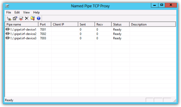
Putty will allow you to enter the named pipe directly into the serial connection, whereas SecureCRT does not allow this, as i’m using SecureCRT I will be using ‘Named Pipe TCP Proxy’ a small utility that allows you to to telnet to a defined port, which then proxies this connection to the pipe. The pipe proxy can be downloaded from http://shvechkov.tripod.com/nptp.html . Using the proxy enables you to easily connect to the serial port from either the local host or a remote machine. The pipe settings are shown below as used in this lab.
To allow you to connect through the new console port and have admin privileges a small amount of configuration is required on the switches.
system-view
[HP-SW1]line aux 0
[HP-SW1-line-aux0]user-role network-admin
[HP-SW1-line-aux0]quit
[HP-SW1]save
We should now be at the point where we have 3 devices running and uplinked to a Cisco router, with console access from our favorite terminal application ready to be configured just like real hardware. The switch configurations to complete the network in this lab topology will be published in a post.